Correlation Power Analysis on AES with an FPGA Sensor
aes source
I ran a final-round correlation power analysis against an AES-128 implementation on a Lattice iCE40HX8K. The setup used a delay-based on-chip sensor, BRAM-backed trace capture, and a bitwise inverse S-box leakage model.
Implementation security, not AES cryptanalysis
This attack does not weaken AES at the algorithmic level. It targets the physical implementation, where internal state transitions change the circuit's switching activity. Conventional power analysis measures supply current or electromagnetic radiation. I instead used a delay-based sensor placed on the FPGA itself.
I used correlation power analysis (CPA) to test whether repeated sensor measurements contained a component that depended statistically on an internal AES value. CPA combines known ciphertexts, a key-dependent leakage hypothesis, and many aligned traces. If the model matches the physical leakage, the correct key hypothesis should correlate more strongly at the sample where that intermediate value affects the device.
| Target | AES-128 final round |
|---|---|
| Platform | Lattice iCE40HX8K |
| Trace width | 56 samples |
| Final dataset | 100,000 traces |
Leakage model
I analyzed one ciphertext byte at a time. For a ciphertext
byte C and a candidate round-key byte K,
the state before the final-round S-box is reconstructed as:
InvSBox(C XOR K)I evaluated each of the eight output bits separately rather than reducing the intermediate value to a Hamming weight. For every bit and each of the 256 key-byte hypotheses, the analysis produced a vector of predicted zero or one values across all encryptions. I then correlated that vector with every sample position using the Pearson correlation coefficient.
This produces a correlation surface indexed by key hypothesis and sample position. A high value alone is not enough. The expected key candidate must separate consistently from its competitors at a physically plausible point in the capture window.
Establishing a known-good analysis path
Before I used the FPGA measurements, I validated the CPA implementation with the reference dataset supplied for the task. I needed this check to separate software-model errors from hardware-measurement problems. Byte ordering, ciphertext reconstruction, inverse S-box indexing, bit extraction, and correlation all had to agree before I could trust the physical experiment.
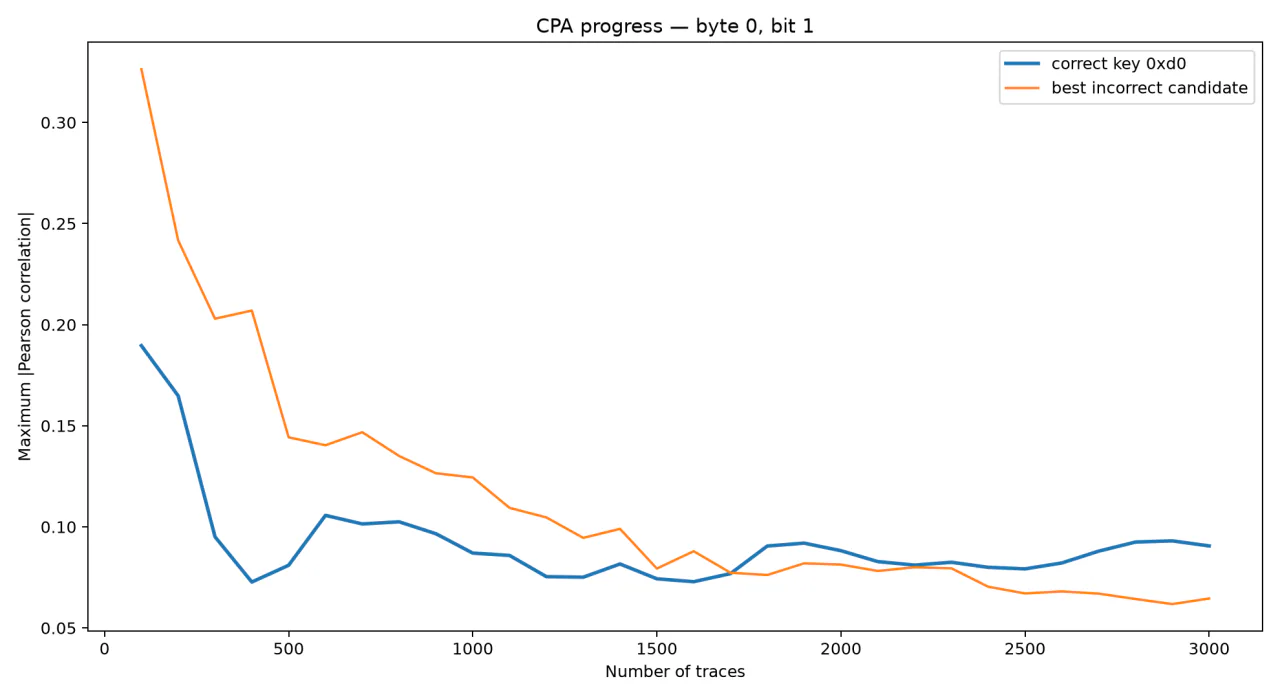
For ciphertext byte 0 and inverse S-box output bit 1, the expected
final-round key byte is 0xd0. Its score becomes
distinguishable after roughly 2,000 traces.
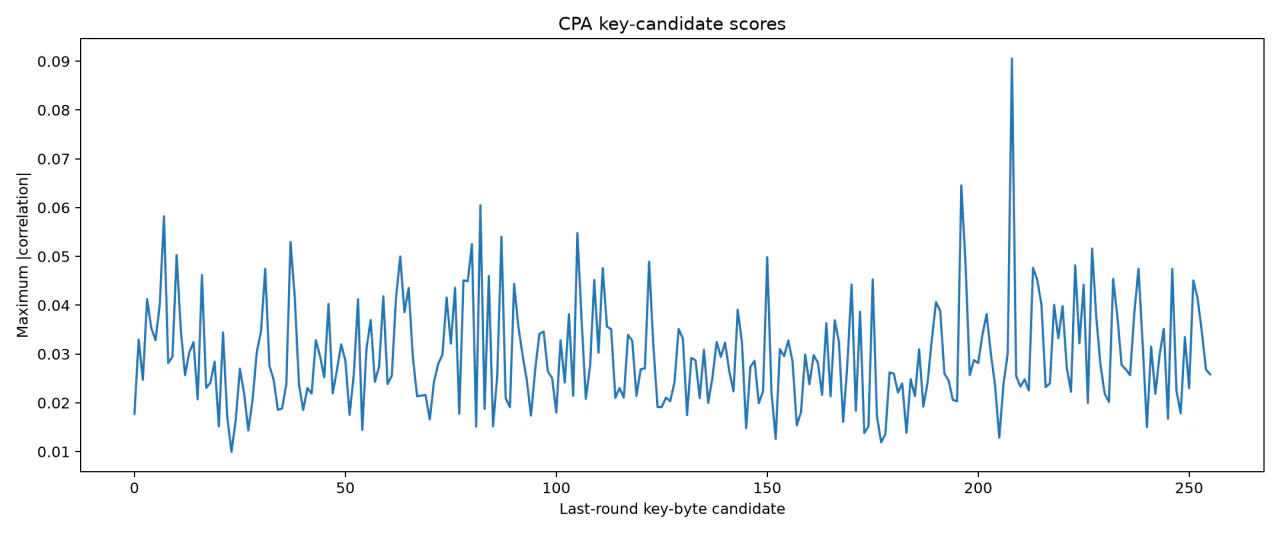
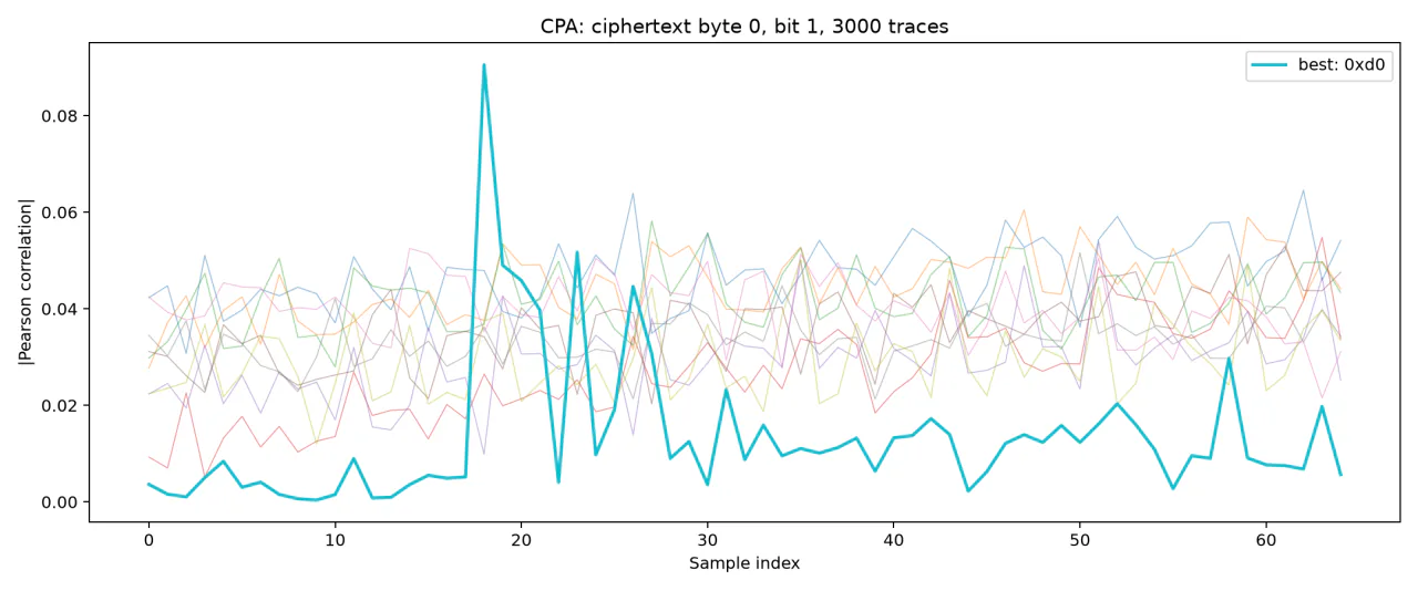
Recovering the expected candidate from the supplied traces gave me a known-good analysis baseline. I could then apply the same final-round model to the noisier traces from the physical FPGA.
Capturing the final AES round
The FPGA design combines the AES core, the delay sensor, one block
RAM, and a UART transport. The measurement logic is implemented in
sense_module.v. A final-round indication from the AES
core is synchronized into the sensor clock domain, then converted into
a bounded capture interval.
On the detected edge, the logic resets the BRAM write address and enables capture. It writes one sensor value per sensor-clock cycle at addresses 0 through 55, then stops after the final write. This gave me exactly 56 samples per encryption without depending on host-side timing.
Once encryption and capture finish, the design sends the 16-byte ciphertext followed by the 56-byte trace over UART. Keeping the ciphertext and measurement in the same transaction keeps their association explicit. A lost byte or an off-by-one read would pair a trace with the wrong cryptographic output and destroy the correlation.
Bring-up and trace acquisition
I started bring-up with a known-answer test from NIST FIPS 197. I would not accept any trace collection until the FPGA returned the expected ciphertext. The same transaction also checked that 56 sensor bytes arrived and that the sensor was operating away from saturation.
Plaintext:  3243f6a8885a308d313198a2e0370734
Ciphertext: 3925841d02dc09fbdc118597196a0b32
The acquisition program generated random 16-byte plaintexts, sent them to the FPGA, and recorded the plaintext, ciphertext, and sensor trace in CSV files. I first collected 3,000 traces to verify framing, dimensions, and numerical variation. The final acquisition contained 100,000 encryptions.
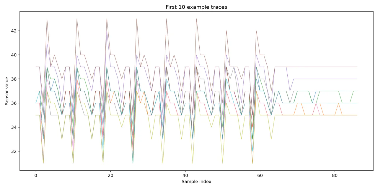
python collect_traces.py -n 100000 -o measurements_100kEach measured trace contained 56 samples with low-amplitude variation rather than rail saturation. That operating point was necessary, but it did not guarantee a successful attack. Most of the observed variance could still be unrelated noise.
CPA over 100,000 FPGA traces
The complete hardware analysis covered 16 ciphertext bytes, eight inverse S-box output bits per byte, 256 key hypotheses, and all 56 sample positions. This corresponds to 128 independent bit-level CPA experiments, each with its own correlation surface.
The expected AES round-10 key was:
abc1d22842e631c999631f6db7805e94
For byte 0 and output bit 4, the expected candidate
0xab produced the largest absolute correlation at sample
8:
Key candidate: 0xab
Correlation:   0.021510
Sample:        8
Trace count:   100000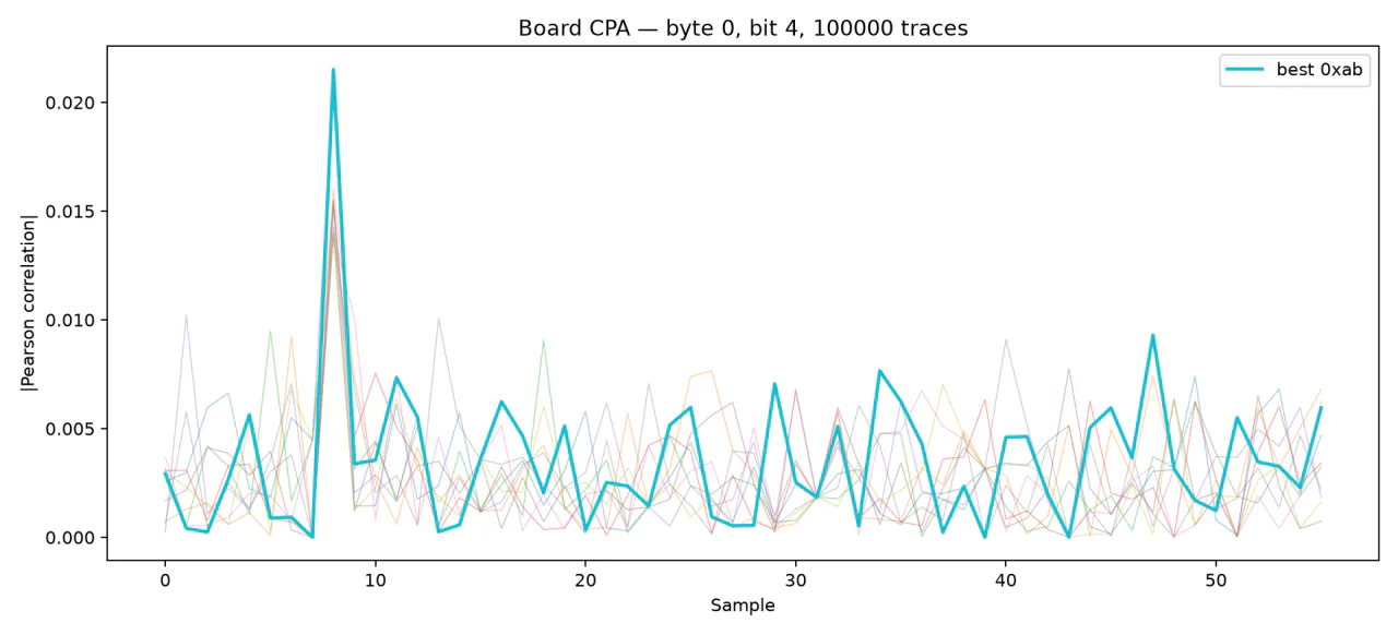
The other bit hypotheses did not produce stable first-ranked recovery. I therefore treat this as evidence of detectable key-dependent leakage, not as a full round-key recovery. I only recovered one bit-level model, and calling the maximum of many noisy correlations a recovered key would overstate the result.
What limited the attack
Signal-to-noise ratio was the main limitation. An on-chip delay sensor observes an indirect consequence of switching activity, and its response depends on placement, routing, clocking, local supply variation, and the chosen capture window. Only a subset of AES state transitions may couple strongly enough into that sensor to be distinguishable from noise.
The strongest sample positions also shifted across ciphertext bytes. This is consistent with serialized or time-distributed activity in the implementation, although I did not isolate the exact cause. A larger attack would need to treat sensor placement and capture timing as experimental parameters rather than fixed constants.
I would repeat the measurements across sensor configurations, tighten timing closure, and try multiple sensing locations. I would also compare trace normalization and bit, Hamming-weight, and Hamming-distance leakage models, since this run did not tell me which change would help most.
What the measurement chain established
The complete measurement chain worked. RTL captured the final-round event, stored sensor values in BRAM, and kept ciphertext and trace framing synchronized over UART. The host implementation then evaluated the same leakage model on the reference and physical datasets.
The AES core returned the correct NIST test vector throughout the experiment. Repeated physical observations still exposed a statistically detectable dependency on one modeled round-key byte. The implementation was functionally correct, but that result alone said nothing about its resistance to side-channel analysis.
References and implementation
- NIST, FIPS PUB 197: Advanced Encryption Standard (AES).
- FPGA implementation, acquisition scripts, and CPA code